History
Aldwyn Brook in the 1950s was a small town at the end of a 15-mile branch line somewhere in the North West of England. Traffic was dwindling until the powers that be decided that Aldwyn Brook would be a good place to build houses and tower blocks for the overspill from the nearby city. Thus it expanded rapidly in the 1960s, which saved the line from the ravages of the Beeching Axe.
Trackplan

Description
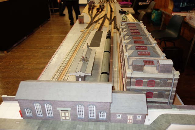
The station comprises a small terminus with an island platform, one side serving the main line and the other a mostly industrial branch. There is a parcels depot (to serve the nearby mail order warehouse) and a small goods yard. Main line trains, mainly freight, going to or from the branch have to reverse in Platform 1. Passenger services on the main line are suburban trains from the junction station, with some express trains from major cities. Parcels trains can originate anywhere from Carlisle to Southampton. The branch line serves several local industries, and there are exchange sidings down the line, where most of the freight from the branch to Aldwyn Brook originates.
Construction
The layout is 4.4m long x 0.6m wide (14 ft 6 in x 2 ft 0 in). There are four baseboards, three scenic and one with a sector plate for the hidden sidings, all supported on folding legs. The baseboards are made mostly from 12mm plywood, with 44mm x 18mm softwood battens, designed for easy set-up and dismantling.
Operation
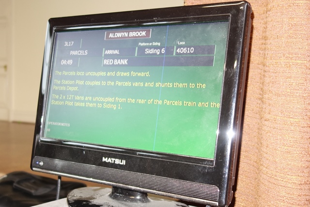
The layout can be operated in various time periods – steam only (1950 – 1968), steam / diesel (1955 – 1968) and diesel only (1969 – 1990s). The station is modelled in the British Rail era, before privatisation, so there will be times when the rolling stock does not match the station signage. The emphasis is on prototypical operation as far as possible and a sequence is available for each period. A monitor is placed at the station end to display arrivals and departures.
Track and signals
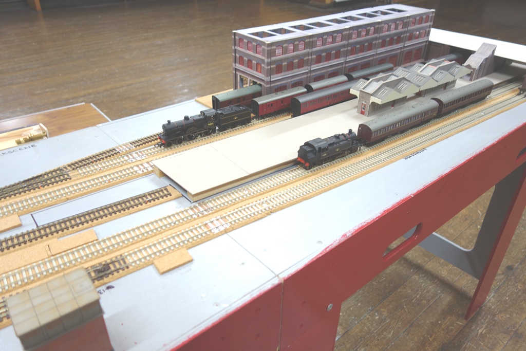
Track is Peco code 75 and all turnouts are live frog type. Uncouplers are fitted to suit hook-and-bar couplings. Turnouts and uncouplers are operated by servo motors. The signals are modern colour light types, using LEDs. The servo motors for the turnouts and uncouplers are linked to Mega Points modules, with master processors mounted in the Control Panel and slave modules mounted below each baseboard. This greatly reduces the amount of wiring required between the Control Panel and the rest of the layout. The signals will be controlled from Arduino modules in a similar way.
Controls
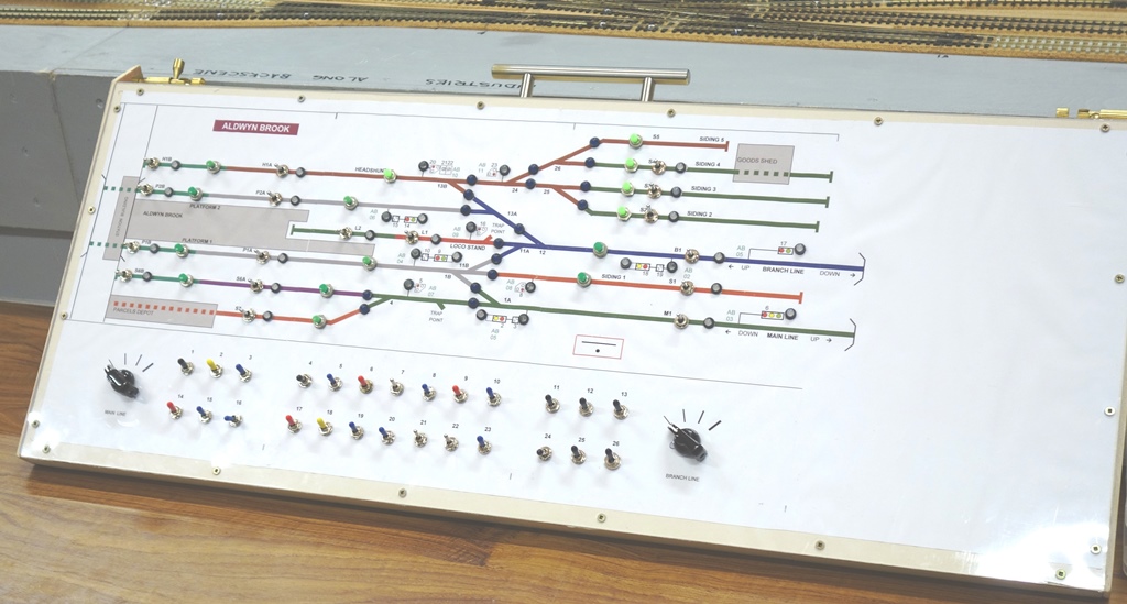
The layout is operated on DC using wired hand held controllers. Provision is made for DCC operation at a later stage. There are two controllers, each of which can be switched to control any part of the track. On the Control Panel, switches for track power and push buttons for the uncouplers are located on the track plan, whilst switches to operate the points and signals are arranged in two rows below the track plan.
Buildings and Scenery
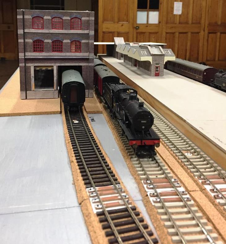
The Booking Office, Platform, Platform waiting rooms, staircase, Goods Shed and Parcels Depot are already built. Lights for the Platform and buildings have been purchased.
Current progress
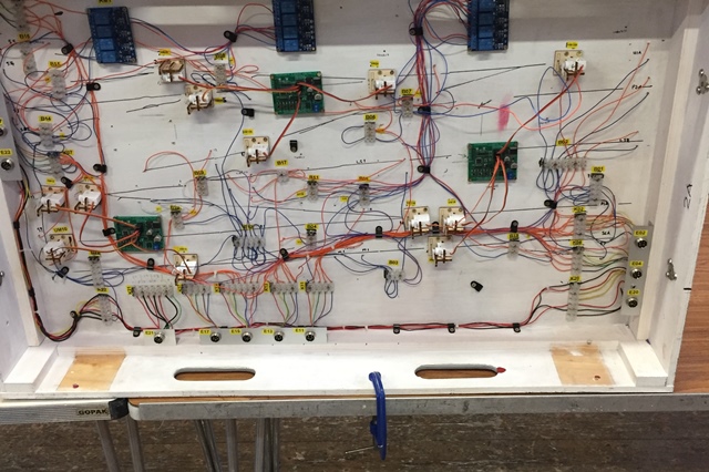
On January 6th 2023 wiring reached the stage where all the turnouts and track sections can be operated from the Control Panel. This marks a significant milestone in the layout development. Over the next few weeks the layout will be fully assembled and tested. The photo (8) shows the MegaPoints Modules (green), Relay Modules (blue) and servos for turnout operation (white). The Relays automatically change the polarity of the live frogs. Work has also started adding cable markers to the wires.
Progress- June 2023
During February and March, the remaining MegaPoints modules were fitted to Boards 1 and 3, and the uncoupler servos were linked to them. The 3-wire Communication Cable was linked via jumper cables from the Control Panel to Boards 1, 2 and 3, and then to the MegaPoints modules. All the turnouts and uncoupler can now be operated from the Control Panel.
First to be tested were the turnout servos. We found that the Operating Wires on the servos were projecting above the level of the rails and locos and stock were sometimes derailed as a result. Investigation revealed this was because the servos had been installed with their Actuating Arms pointing downwards. The solution was to reset the Actuating Arms so they were pointing upwards, so the only time the Operating Wires were above rail level was when the turnouts were moving across from one position to the other.
Another milestone was reached on 21st April 2023, when all the uncouplers could be operated from the Control Panel. The uncouplers are operated by Push Buttons from the Control Panel.
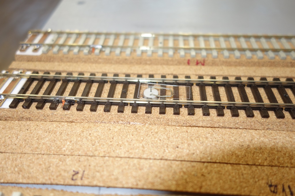
The vehicles to be uncoupled are pushed over the uncoupler ramp, ensuring the coupler bars are touching.
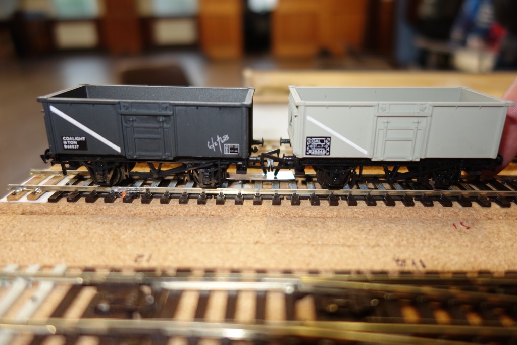
The vehicles can now be separated and the Uncoupler Button released, so the ramp will return to the lowered position.
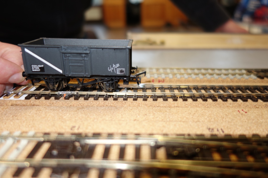
This means the layout is now fully operational.
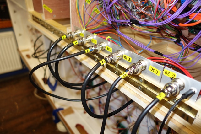
Identification labels have been fitted to the Jumper Cables so each cable can be matched to the corresponding number on the sockets.
Open Day Saturday 17 June 2023
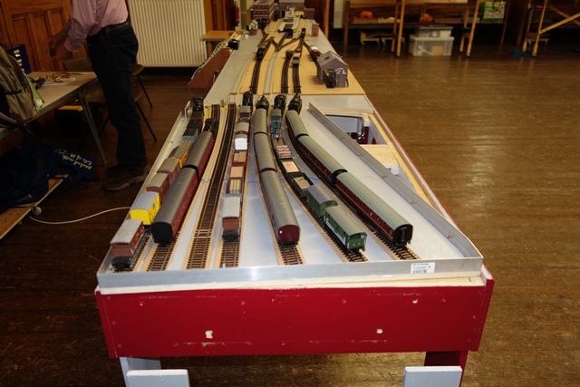
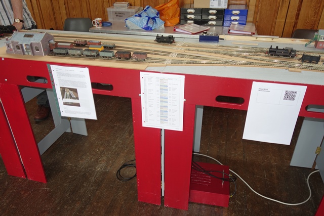
This was the first time the layout had been operated in full working order in public. It was very gratifying to see that everything worked successfully apart from a couple of minor faults, which were fixed the following Friday. The first complete sequence lasted four hours, although a lot of this was because we were talking to the public and familiarising ourselves with the Control Panel. Photos below show the layout being set up on the Friday night before the open Day. The Train Describer (see Photo) was a big talking point.
Progress
One of the issues noted on the Open Day involved the uncouplers. Steel piano wire had been used to link the servos to the uncoupler ramps. This wire proved to be very stiff and caused some of the uncoupler ramps to twist as they were raised and lowered. The solution has been to replace the steel wire with brass wire, which is much more flexible.
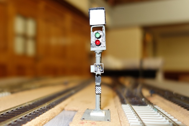
Following the Open Day, work has concentrated on installing and wiring the signals. All the Running Signals were custom built by TM, a founder member, (see Photo below for an example), whilst the Position Light Signals are commercial products from Train Tech.
Some of the Running Signals have working Theatre-type Route Indicators. These advise the train driver which route is set. They are only lit when the main aspect is Green. Some Running Signals also have Call-on Signals attached to the signal post. Call-on Signals comprise two white lights at 45 degrees and can only be lit when the main aspect is Red. These advise the train driver to proceed slowly only as far as he can see the line to be clear. They are used, for example, when shunting stock into an already occupied platform.
There are five Position Light Signals (“ground signals”) on the layout. These have three small lights, one red and two white. The Stop indication is one Red and one White light, displayed horizontally. The Proceed aspect is two White lights at 45 degrees. They control movements between sidings, and from sidings to the main line or branch line.
Four-relay modules were purchased, four modules in total. In addition, two Megapoints Frog and Relay Driver modules were purchased. These modules are used together to ensure the signals will only display the correct aspect according to the way the turnouts are set.
The Megapoints modules are connected to the Communications Cable which is linked to the Control Panel. All the instructions from the Control Panel Switches are sent via the Megapoints Master Control module and the 3-wire Communications Cable to all the Megapoints modules located under each board in sequence. The four Frog and Relay modules are linked to the Relay Modules using 6-wire cables and sockets. All this has required a lot of additional wiring.
At the time of writing, all the signals on Board 2 are working, including the Position Light Signals, and all that remains is to adjust the values of the resistors for the LEDs to give the correct brightness.
Future
The Signals on Board 3 will be tackled next. Running nights will follow to check that everything works as it should. Ballasting, scenery, etc., will follow after that.